Norcim rc electronics club page 4…….

![]()
![]()
![]()
SOME USEFUL LINKS ![]() HobbyCity
HobbyCity
![]() GreatHobbies
GreatHobbies ![]() BangGood
BangGood
![]() ModelFlight RC
ModelFlight RC
![]() HorizonHobby
HorizonHobby
ECONOMY ELECTRIC FLIGHT was outlined in Radio1 and Radio2 pages.
Well the picture shows one of the test models,
a  ‘Graupner Biene’,
using the ‘Sun’ motor, on a typical climb to thermal height, and it will do this
twice on seven GPâ AA nickel hydride cells from CPC
electronics.com at just £1.00 per cell. With the motor costing
just £2.30 from JPR electronics, this shows just how
inexpensive good electric flight can be. The AA cells give around ten minutes
of full power in the air using a Perkins Distribution (most model shops) 8x5.5 electric flight prop. Increased
climb rate can be had, by using a Graupner 9x5 (most
model shops) electric flight prop, but this reduces ‘full power’ in the air to
around 8 minutes. Increased performance can be had with a Groaupner speed 600 motor and a standard 6 cell sub C
battery pack. (see page 2)
‘Graupner Biene’,
using the ‘Sun’ motor, on a typical climb to thermal height, and it will do this
twice on seven GPâ AA nickel hydride cells from CPC
electronics.com at just £1.00 per cell. With the motor costing
just £2.30 from JPR electronics, this shows just how
inexpensive good electric flight can be. The AA cells give around ten minutes
of full power in the air using a Perkins Distribution (most model shops) 8x5.5 electric flight prop. Increased
climb rate can be had, by using a Graupner 9x5 (most
model shops) electric flight prop, but this reduces ‘full power’ in the air to
around 8 minutes. Increased performance can be had with a Groaupner speed 600 motor and a standard 6 cell sub C
battery pack. (see page 2)
The following circuit shows a simple speed
controller. Many of these controllers have now been used with test models using
Micron receivers and all have 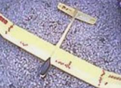 performed well. The few
components of the controller allows home construction for less than £3.00! The
controller is based around a CD4001N quad 2-input NOR gate IC which can cost as
little as 30p from your electronics store! The real expensive bit is the MOSFET
output transistor which could lay you back around £2.50. The single MOSFET
drives the SUN motor (including standard 380 and 540 motors) using seven cells
(8.4volts) with no problem. You can even cut the metal tag off the transistor
to make the controller more compact, without overheating of the MOSFET.
performed well. The few
components of the controller allows home construction for less than £3.00! The
controller is based around a CD4001N quad 2-input NOR gate IC which can cost as
little as 30p from your electronics store! The real expensive bit is the MOSFET
output transistor which could lay you back around £2.50. The single MOSFET
drives the SUN motor (including standard 380 and 540 motors) using seven cells
(8.4volts) with no problem. You can even cut the metal tag off the transistor
to make the controller more compact, without overheating of the MOSFET.
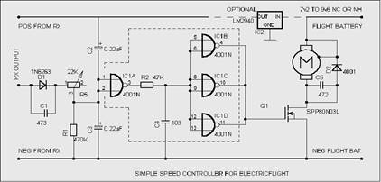 The input circuitry produces a saw-tooth waveform with each
servo pulse. This can be adjusted via trimmer R5 to trigger IC1A gate to
produce a 50/50 mark space output thus driving the motor at half speed. Changes
in the pulse width cause the saw-tooth waveform level to change giving variable
speed from fully ON through variable to fully OFF condition. The circuit
without the optional 5v regulator is intended for use with a separate receiver
battery. If the LM2940 is fitted then the receiver, servos and controller are
supplied by the flight battery.
The input circuitry produces a saw-tooth waveform with each
servo pulse. This can be adjusted via trimmer R5 to trigger IC1A gate to
produce a 50/50 mark space output thus driving the motor at half speed. Changes
in the pulse width cause the saw-tooth waveform level to change giving variable
speed from fully ON through variable to fully OFF condition. The circuit
without the optional 5v regulator is intended for use with a separate receiver
battery. If the LM2940 is fitted then the receiver, servos and controller are
supplied by the flight battery.
This simple circuit is more suited to receivers with full rail voltage output pulses (usually Cmos decoder chips) and has been tested using Micron, Fleet and RCM+E receivers.
Using the three remaining gates of the CD4001BCN in parallel gives adequate drive for up to five MOSFETs in parallel for ‘hot’ motors. (at the relatively low switching speeds!).
D2 and C5 provide good suppression of motor interference for the Sun motor, which has no internal brush suppression capacitors. For ‘Hot’ genuine electric flight motors just follow the suppression instructions supplied with the motor.
IT’S SERVO TESTER TIME!
The following circuit offers manual control of almost any make of R/C servo, using just a receiver battery (4.8 nicad) for power. The components should cost you no more than a £1.50 or just over 2 Euros! and it should work with all makes of servo. The circuit is a text-book ‘two transistor multivibrator’ providing an 18 to 20ms cycle time which suits R/C servos. The circuit is however extremely lob-sided! In that one side produces around 17ms delay before triggering the other side, which only stays on for 1.5ms! It’s this side that the servo output is taken from. The 4k7 pot with knob, produces a pulse variation from 1ms to 2ms at the output which can be used to test most known servos. C3 provides sufficient damping of servo noise to let the circuit work correctly. It’s worth mentioning that the hfe of the transistor used must be high, better than 250 @ 1ma. So if substituting, then pick a high gain device.
THOUGHTS ARE NOW WITH FAST CHARGING NICAD AND NICKEL HYDRIDE BATTERIES
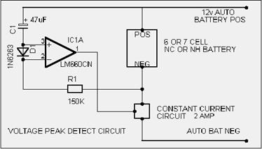 There are several methods of fast
charging model car and ‘electric flight‘ batteries but
the most popular system, is called the ‘Voltage Peak Detect Method’. When NC or
NH batteries are charged, their voltage slowly rises to a peak (when fully
charged) but this is quickly followed by a small but significant dip in the
battery voltage. ‘Peak detect’ fast chargers, rely on their ability to detect
this small voltage drop when the nicad is full and
terminate the charge before overcharge damage is done. A simple ‘peak detect’
method for six or seven cell sub-C batteries is shown. At switch-on,
(connection to the 12v supply), the forward volts of D1 holds the inputs of the
OP AMP apart, preventing any switching of the output. Initially, the voltage
across D1 (which is a Schottky RF diode) can be as high as 0.3v but this
quickly reduces within minutes to less than 0.05 volts because of the extremely
low current flow through the diode. C1 then, follows the increasing nicad voltage (which can be as
close as 0.02 volts when near to full charge). At full charge, the nicad voltage begins to fall…..D1
soon becomes reversed, (also IC1A inputs!) causing IC1A output to ‘flip’. This
terminates the charge current. The result is a fast, half to one hour,
automatic cut-off charge! There is no need to discharge the nicad first. Full charge is detected even with a
partly charged nicad. It
is important that C1 is one of the recent Aluminium Electrolytic low
leakage type capacitors. (Rubicon TWL series 47UF16V-16TWL47MO811 Farnell order
code 499-067). It’s worth mentioning that the 1N6263 has a lower reverse
leakage current than general purpose schottky diodes.
This helps at the peak detect point.
There are several methods of fast
charging model car and ‘electric flight‘ batteries but
the most popular system, is called the ‘Voltage Peak Detect Method’. When NC or
NH batteries are charged, their voltage slowly rises to a peak (when fully
charged) but this is quickly followed by a small but significant dip in the
battery voltage. ‘Peak detect’ fast chargers, rely on their ability to detect
this small voltage drop when the nicad is full and
terminate the charge before overcharge damage is done. A simple ‘peak detect’
method for six or seven cell sub-C batteries is shown. At switch-on,
(connection to the 12v supply), the forward volts of D1 holds the inputs of the
OP AMP apart, preventing any switching of the output. Initially, the voltage
across D1 (which is a Schottky RF diode) can be as high as 0.3v but this
quickly reduces within minutes to less than 0.05 volts because of the extremely
low current flow through the diode. C1 then, follows the increasing nicad voltage (which can be as
close as 0.02 volts when near to full charge). At full charge, the nicad voltage begins to fall…..D1
soon becomes reversed, (also IC1A inputs!) causing IC1A output to ‘flip’. This
terminates the charge current. The result is a fast, half to one hour,
automatic cut-off charge! There is no need to discharge the nicad first. Full charge is detected even with a
partly charged nicad. It
is important that C1 is one of the recent Aluminium Electrolytic low
leakage type capacitors. (Rubicon TWL series 47UF16V-16TWL47MO811 Farnell order
code 499-067). It’s worth mentioning that the 1N6263 has a lower reverse
leakage current than general purpose schottky diodes.
This helps at the peak detect point.
NEXT THOUGHTS ARE WITH CHECKING TRANSMITTER RANGE
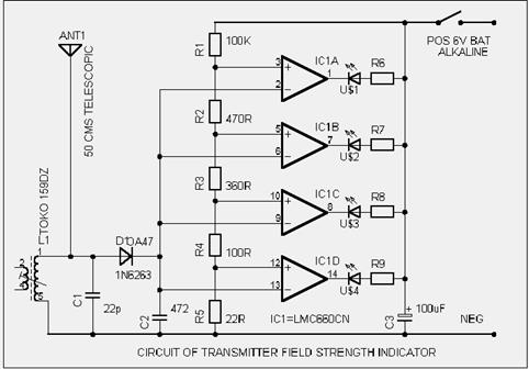 This next circuit lends itself
not only for home checking but also club and quick model shop checks. The
circuit checks for correct power output of any 35 or 40 MHz radio
control transmitter is shown. These things are called ‘field strength meters’
and are a standard piece of electronic equipment in the service workshop to
check the output power of R/C transmitters. ‘Field Strength Meters’ (as they
are called) are usually based around a reasonable size sensitive 50uA moving
coil panel meter. These are now listed (Farnell) between £20 and £30 each
(before circuitry!). This circuit is based around the National Semiconductor
LM661CN Cmos quad op-amp IC. The circuitry components
should cost no more than £4.00! and it has greater
sensitivity than the standard meter type. Transmitter output strength is shown
by four Superbright red light emitting diodes. A correctly
functioning R/C transmitter, will illuminate three to four LEDs at a distance
of 10 metres away. Adjusting the length of the short telescopic aerial will
allow all LEDs to operate at a shorter distance for indoor checking. With
occasional use, a four AA alkaline battery lasts over a year
This next circuit lends itself
not only for home checking but also club and quick model shop checks. The
circuit checks for correct power output of any 35 or 40 MHz radio
control transmitter is shown. These things are called ‘field strength meters’
and are a standard piece of electronic equipment in the service workshop to
check the output power of R/C transmitters. ‘Field Strength Meters’ (as they
are called) are usually based around a reasonable size sensitive 50uA moving
coil panel meter. These are now listed (Farnell) between £20 and £30 each
(before circuitry!). This circuit is based around the National Semiconductor
LM661CN Cmos quad op-amp IC. The circuitry components
should cost no more than £4.00! and it has greater
sensitivity than the standard meter type. Transmitter output strength is shown
by four Superbright red light emitting diodes. A correctly
functioning R/C transmitter, will illuminate three to four LEDs at a distance
of 10 metres away. Adjusting the length of the short telescopic aerial will
allow all LEDs to operate at a shorter distance for indoor checking. With
occasional use, a four AA alkaline battery lasts over a year 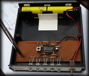 (even
occasionally leaving the thing switched on)
(even
occasionally leaving the thing switched on)
The OA47 diode seems to work best but more difficult to get. L1 needs to be initially adjusted to illuminate the maximum number of LEDs at a range of 10 metres or so. Once set that’s it. The Toko coil used is no longer manufactured but many are still in the pipeline and there are alternatives. Remember, if you set L1 using a 35MHz Tx then the unit will only check other 35MHz transmitters. If 40MHz Txs are to be checked, set L1 using a 40MHz Tx. L1/C1 form a tuned circuit at 35MHz. A 35MHz Tx will excite this coil and cause a resonance of L1. D1 detects this and a little current flows at 35 million times a second! into C2. This increases the voltage across C2 (slightly) in proportion to the power of the transmitter signal. The LMC660CN is a Cmos op-amp and has little effect on the input circuit. The op-amps are arranged as voltage comparators using the potential divider R1-R5. The resistor values are selected to give a 3dB step between op-amps flipping on. (each one showing twice the transmitter power output) So with a weak signal, IC1D output will illuminate LED4. As the received signal gets stronger, the remaining LEDs will illuminate in turn, until all four are illuminated.
WITH IT’S MANY ADVANTAGES, 2.4 GIGAHERTZ RADIO CONTROL SYSTEMS ARE NOW VERY POPULAR.
The above Field Strength Meter based on the LMC660 rapidly runs out of Puff after the 40MHz band. This leaves the 72MHz and the now popular 2.4Gigahertz bands not detectable. DAVE1993 of RCGroups.com has done some work producing a really interesting Broad-Band Field Strength Meter. This detects from 27MHz to around 5 GIGAHERTZ ! Dave’s posting in the RCGroups.com website is http://www.rcgroups.com/forums/showthread.php?t=1557232 His posting links to other threads that started and compliment the discussion.
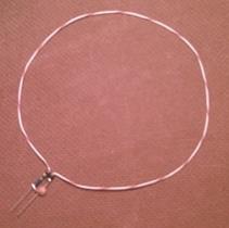
FIELD STREGTH METERS are essentially comparative devices. They simply compare ‘like with like’. The above LMC660 FSM compares 35 and 40MHz transmitter output at a distance of 10 metres away. The DAVE1993 transmitter Field Strength Meter compares transmitter output at a much closer range (as shown in the picture). However the result of testing is the same. If a known ‘good’ Tx gives a reading of ‘X X . XX’ when positioned as shown in the picture….then a ‘suspect’ transmitter should give a similar reading when positioned in the same place. The following pictures are courtesy of the man himself…DAVE1993. Note that there is much more detail using the link above.
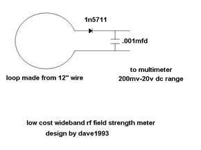
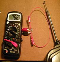
The possibility of using DAVE1993’s circuit in place of the TOKO coil version in the LMC660 circuit above,
does come to mind !
FURTHER THOUGHTS NOW RE: THE FAST NICAD AND NH CHARGER ABOVE Ooops…two above!
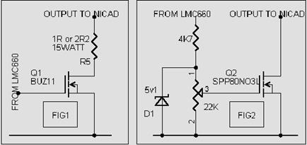 Fig 1 shows a possible output stage
for charging a 7v2. nicad.
Note that this is not a ‘constant current’ circuit but should work OK. Note
that the 1R resistor will initially let through a charge current of around 3
Amps which will slowly fall to 1 Amp or less at peak detection. The MOSFET in
this version would not need to be fastened to a heat sink as it is in a fully
‘on’ condition when charging and will need to dissipate little heat. The 1R or
2R resistor however will get very hot and would benefit from a heat sink. The
1R resistor value should be used for sub-C nicads.
The 2R2 resistor is a better value with less current flow for 7v2 AA nicads. Fig 2 shows another possible output circuit in
which the charge current through the MOSFET (Q2) can be set by adjustment of
the 22K trimpot. A charge rate of 2 Amps is suggested
for 7v2 nicad batteries.
Some care will be required with the setting of the 22K pot and best to start
with the wiper at the negative end of the pot. The charge rate should be
reasonably constant with this circuit, owing to the bias characteristics of
MOSFETs. Note that this circuit uses the MOSFET (Q2) to restrict the charge current
flow and therefore Q2 will get hot! AND will need to be clamped to a metal heat
sink. IT MUST BE POINTED OUT THAT ALTHOUGH THE ‘PEAK VOLTAGE DETECTION CIRCUIT’
HAS BEEN WELL TRIED USED TO DATE, THE TWO ABOVE CIRCUITS FIG1 & FIG2 ARE
‘POSSIBLE OUTPUT’ CIRCUITS AND ARE INCLUDED FOR EXPERIMENT.
Fig 1 shows a possible output stage
for charging a 7v2. nicad.
Note that this is not a ‘constant current’ circuit but should work OK. Note
that the 1R resistor will initially let through a charge current of around 3
Amps which will slowly fall to 1 Amp or less at peak detection. The MOSFET in
this version would not need to be fastened to a heat sink as it is in a fully
‘on’ condition when charging and will need to dissipate little heat. The 1R or
2R resistor however will get very hot and would benefit from a heat sink. The
1R resistor value should be used for sub-C nicads.
The 2R2 resistor is a better value with less current flow for 7v2 AA nicads. Fig 2 shows another possible output circuit in
which the charge current through the MOSFET (Q2) can be set by adjustment of
the 22K trimpot. A charge rate of 2 Amps is suggested
for 7v2 nicad batteries.
Some care will be required with the setting of the 22K pot and best to start
with the wiper at the negative end of the pot. The charge rate should be
reasonably constant with this circuit, owing to the bias characteristics of
MOSFETs. Note that this circuit uses the MOSFET (Q2) to restrict the charge current
flow and therefore Q2 will get hot! AND will need to be clamped to a metal heat
sink. IT MUST BE POINTED OUT THAT ALTHOUGH THE ‘PEAK VOLTAGE DETECTION CIRCUIT’
HAS BEEN WELL TRIED USED TO DATE, THE TWO ABOVE CIRCUITS FIG1 & FIG2 ARE
‘POSSIBLE OUTPUT’ CIRCUITS AND ARE INCLUDED FOR EXPERIMENT.
A POWER SWITCH FOR R/C RECEIVERS
Fig
3 shows a simple circuit that can be plugged into one of the receiver servo
outputs to switch on and off an external load of up to 15 Amps. The circuit is
shown driving an electric flight motor but for boat people the relay could
switch several torch bulbs, or a high power halogen lamp, or winch, or sound
circuit. The dotted line shown from  the
relay back contact to ground provides dynamic braking of the motor when using
folding props with electric flight. The input components form a text-book
‘diode pump’ circuit. The trim-pot is set so that thin pulses from the
transmitter pump up C1 voltage to just get the Logic Level MOSFET,
conducting. The current flow through the relay however, is very small and well
below that necessary to close the relay contacts. But throwing the stick at the
transmitter to get fat pulses, increases the voltage across C1, allowing much
more current flow through the MOSFET and the relay closes. Both 5 volt and 6
volt relays have been used in this circuit with windings of 55R to 90R. Notice
that only the Rx pulse input and the negative input is required from the
receiver (The red positive input is simply left unconnected). The current drain
of the circuit on the receiver battery is almost undetectable. At higher
voltages of the external circuit, the MOSFET (Q1) tends to limit the current
flow through the relay to acceptable levels. The MOSFET, RFD4N06L (or similar)
is a TO 251 (I-Pak) device and may get warm with a 12 volt external supply.
This is normal. Several relays are suitable…finder type SPCO 16A Farnell
code 431-308…or smaller 12Amp version finder type Low profile 21 series
Farnell code 321-0224. Smaller low profile relays are now available and should
be suitable.
the
relay back contact to ground provides dynamic braking of the motor when using
folding props with electric flight. The input components form a text-book
‘diode pump’ circuit. The trim-pot is set so that thin pulses from the
transmitter pump up C1 voltage to just get the Logic Level MOSFET,
conducting. The current flow through the relay however, is very small and well
below that necessary to close the relay contacts. But throwing the stick at the
transmitter to get fat pulses, increases the voltage across C1, allowing much
more current flow through the MOSFET and the relay closes. Both 5 volt and 6
volt relays have been used in this circuit with windings of 55R to 90R. Notice
that only the Rx pulse input and the negative input is required from the
receiver (The red positive input is simply left unconnected). The current drain
of the circuit on the receiver battery is almost undetectable. At higher
voltages of the external circuit, the MOSFET (Q1) tends to limit the current
flow through the relay to acceptable levels. The MOSFET, RFD4N06L (or similar)
is a TO 251 (I-Pak) device and may get warm with a 12 volt external supply.
This is normal. Several relays are suitable…finder type SPCO 16A Farnell
code 431-308…or smaller 12Amp version finder type Low profile 21 series
Farnell code 321-0224. Smaller low profile relays are now available and should
be suitable.
EVER LOST A MODEL IN A CORN FIELD??? Well this next 555 circuit will detect its position!
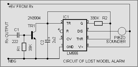 PIEZO SOUNDER DEVICES ARE SMALL AND
WEIGH JUST 5gms! These
small units can be heard up to 100 metres away in quiet countryside conditions,
particularly if they are switched on and off! The following circuit uses a 30p
555 timer IC, to drive one of these Piezo sounders. The 555 is configured as a
50/50 astable pulse generator which sounds the piezo
thing around once a second. Transistor TR1 keeps shorting C2 with each servo
pulse, so that the 555 IC can’t get going. The piezo sounder remains quiet
during normal flight conditions. Should the model decide to land in a corn or
rapeseed field, then switching off the Tx allows TR1
to go open circuit and C2 to begin its charge/discharge cycle enabling the 555
to switch the piezo sounder on and off at around once per second. With careful
listening, the model can be located! Suitable piezo sounders are Farnell order
code 927-181 or 927-119. The receiver input stage should suit most makes of
receiver including those with low voltage servo pulse output.
PIEZO SOUNDER DEVICES ARE SMALL AND
WEIGH JUST 5gms! These
small units can be heard up to 100 metres away in quiet countryside conditions,
particularly if they are switched on and off! The following circuit uses a 30p
555 timer IC, to drive one of these Piezo sounders. The 555 is configured as a
50/50 astable pulse generator which sounds the piezo
thing around once a second. Transistor TR1 keeps shorting C2 with each servo
pulse, so that the 555 IC can’t get going. The piezo sounder remains quiet
during normal flight conditions. Should the model decide to land in a corn or
rapeseed field, then switching off the Tx allows TR1
to go open circuit and C2 to begin its charge/discharge cycle enabling the 555
to switch the piezo sounder on and off at around once per second. With careful
listening, the model can be located! Suitable piezo sounders are Farnell order
code 927-181 or 927-119. The receiver input stage should suit most makes of
receiver including those with low voltage servo pulse output.
AND WHERE IT ALL BEGAN!
Did
you know that one of the first offerings from the ‘Micron people’ was a
pulse proportional system? Based around a ‘Mighty Midget’ electric motor?
Full kits were available from around 1962! The system used a single
electric motor to pulse both rudder and elevator 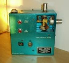 control surfaces. Surprising
proportional flight could be achieved with this system, which was termed
‘Galloping Ghost’ (because of the noise of the flapping control surfaces!). One
of the flight demonstrations of the system, involved several passes through
soccer goalposts (at a medium throttle setting, as there was no throttle
control), which was quite an achievement alongside the standard ‘reed’
equipment of the day. The original Gallatrol
transmitter circuit is shown in page9.
control surfaces. Surprising
proportional flight could be achieved with this system, which was termed
‘Galloping Ghost’ (because of the noise of the flapping control surfaces!). One
of the flight demonstrations of the system, involved several passes through
soccer goalposts (at a medium throttle setting, as there was no throttle
control), which was quite an achievement alongside the standard ‘reed’
equipment of the day. The original Gallatrol
transmitter circuit is shown in page9.
 The
receiver (shown bottom left) used a super-regen front end (only allowing one
model to fly at a time!) was designed by early R/C pioneer, Doug Bolton.
Other R/C equipment of the day used self-centre toggle switches on the front of
the transmitter for full throw of the control surfaces Joystick units
had not been invented! So joysticks for the ‘Micron people’ transmitter
kits had to be individually made from brass stock with piano wire wound
springs! Two external pots provided the in-flight trims. Early transmitter
circuitry used a variable rate saw-tooth generator (unijunction) followed by a
varying level Schmitt trigger to generate the mark/space and pulse/rate, pulses
for the ‘mighty midget’ actuator. Later circuitry used a curious diode gated
two-transistor astable-multivivrator, which gave a
logarithmic effect to the rate channel
The
receiver (shown bottom left) used a super-regen front end (only allowing one
model to fly at a time!) was designed by early R/C pioneer, Doug Bolton.
Other R/C equipment of the day used self-centre toggle switches on the front of
the transmitter for full throw of the control surfaces Joystick units
had not been invented! So joysticks for the ‘Micron people’ transmitter
kits had to be individually made from brass stock with piano wire wound
springs! Two external pots provided the in-flight trims. Early transmitter
circuitry used a variable rate saw-tooth generator (unijunction) followed by a
varying level Schmitt trigger to generate the mark/space and pulse/rate, pulses
for the ‘mighty midget’ actuator. Later circuitry used a curious diode gated
two-transistor astable-multivivrator, which gave a
logarithmic effect to the rate channel 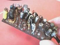 (elevator). This improved the elevator
effect when using the ‘mighty midget’ actuator. Unfortunately this effect could
not be used with the later more popular American Rand actuator.
(elevator). This improved the elevator
effect when using the ‘mighty midget’ actuator. Unfortunately this effect could
not be used with the later more popular American Rand actuator.
Rapidly advancing multi-channel analogue and digital technology saw the demise of this kind of simple pulse proportional control but there is little doubt that these early systems began the trend into true proportional control of model aircraft.
The photos show one of the early Micron People ‘Galloping Ghost’ proportional systems, which is now fifty years old! When last tested with replaced nicad batteries…….It still worked!….and without any doubt, it would still fly a model through those soccer goalposts! Unfortunately my grey matter has slowed down somewhat and there is no way now of proving this!
A
photo of one of the models that flew with this system is shown and probably
dates around 1962 ish. Although looking good, it was
found that the pulsing of the radio system was clearly seen when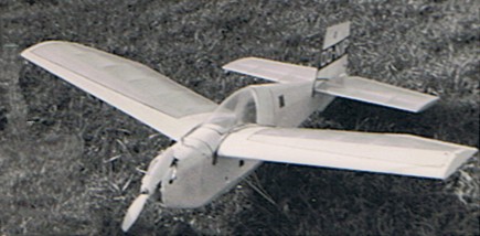 flying. Other models used at
the time were the ‘Gasser’ and the Charles Rail design called ‘Galloper’ both
were plans from the Aeromodeller magazine. The
conclusion was that the greater length of the fuselage from the wing to the
tail actually helped to damp out any visual ‘hopping’ effect of the elevator.
The use of a heavy motor, prop and motor mounting plate also helped. This
produced a situation of having to add lead to the tail of the model to get the
correct CG. This extra weight at the tail end dampened out the pulsing elevator
effect. The pulsing rudder never seemed a problem and under all flying
conditions could not be noticed when flying.
flying. Other models used at
the time were the ‘Gasser’ and the Charles Rail design called ‘Galloper’ both
were plans from the Aeromodeller magazine. The
conclusion was that the greater length of the fuselage from the wing to the
tail actually helped to damp out any visual ‘hopping’ effect of the elevator.
The use of a heavy motor, prop and motor mounting plate also helped. This
produced a situation of having to add lead to the tail of the model to get the
correct CG. This extra weight at the tail end dampened out the pulsing elevator
effect. The pulsing rudder never seemed a problem and under all flying
conditions could not be noticed when flying.
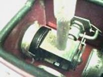
Memories of early galloping ghost models that I flew, showed that they were extremely good at slow flying during the glide after the motor had cut. In fact I remember that with one model, I could often bring round into wind with the intention of landing several yards in front of me, but Full Up elevator at that point produced a slow fully controlled rise into my chest where the model was ‘caught’. I never achieved this with later models fitted with proportional gear. One reason could be that GG models were built of balsa and tissue covered (they were light!). On reflection an additional reason for this uncanny control could be the fact that at extremely low speeds, the wing was continually stalling and uninstalling with the ‘hopping’ effect of the elevator at full UP of the system. (generally the elevator is kicked UP around twice a second with full UP joystick and hopping is noticeable). The GG actuator (or servo) designs of the time mostly used a Mighty Midget electric motor with its nylon top gear. This allowed light spring centring. The drawing shows a typical modified version by Terry Tippett. The centring used a spring similar to that seen on joysticks today but instead of stretching the spring, it was simply twisted clock and anti-clockwise of its natural un loaded state. The nylon gearwheel had a 6BA nut bolt fitted at the 12 o’clock position with a short bit of fuel tube which stopped rotation of the motor in either direction by resting on the motor body. At slow pulse rates this brief ‘resting time’ on the motor body lengthened the time that the elevator stayed in the ‘UP’ position. This allowed powered loops with the system.
The hole at the back of the fuselage was purposely made large to aid the final adjustments of the elevator angles. When correct the brass tube was positioned with balsa inserts and cemented in place. This now historic radio control system flew alongside ‘Reed Systems’ of the time. On many occasions the ‘Gallatrol’ system would be demonstrated flying backwards and forwards through Soccer goalposts! The following drawings show the typical oscillation of the 6BA nut bolt fitted at the 12 o’clock position of the nylon gearwheel, alongside transmitter joystick positions. The bolt had fuel tube pushed on and acted as a rotation ‘stop’ when reaching the motor body during FULL ‘UP’ condition. (see bottom left drg).
EXPECTED OSCILATION OF THE MM GEARWHEEL AT VARIOUS JOYSTICK POSITIONS.
Interested?......then here are some links to the historic Galloping Ghost system with even a video !
THE MIGHTY MIDGET SERVO (OR ACTUATOR ?) WAS ALSO USED FOR SIMPLE SINGLE CHANNEL GIVING PROPORTIONAL LEFT/RIGHT RUDDER.
In
this system the pulse rate from the transmitter was usually fixed around 10
cycles per second of a ‘Tone’ followed by an equal time of carrier (27MHz).The
tone was around 1000 cycles per second. (a kind of Low
whistle!) This ‘equal’ Tone/Carrier would 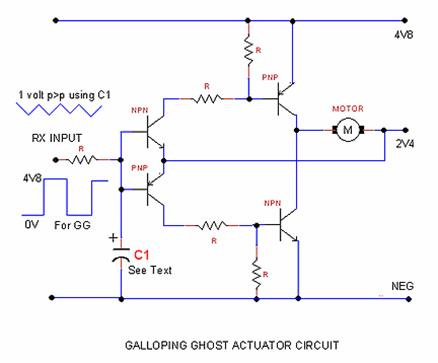 oscillate the motor actuator (and the
rudder) around 10 degrees about centre position (centring was caused by a light
spring). Left/Right Movement of the single joystick at the transmitter, altered
the length of the Tone compared with the carrier. This was called proportional
mark/space transmission. The motor actuator responded by pulsing proportionally
left or right.
oscillate the motor actuator (and the
rudder) around 10 degrees about centre position (centring was caused by a light
spring). Left/Right Movement of the single joystick at the transmitter, altered
the length of the Tone compared with the carrier. This was called proportional
mark/space transmission. The motor actuator responded by pulsing proportionally
left or right.
A DOWNSIDE of this simple system was Battery drain. Not only was the electric motor continually running but its direction was changing ten times a second ! The current required to reverse an electric motor that is going in one direction is many times its normal running current. A 500mah DEAC rechargeable battery of the day would only last a couple of flights. A typical receiver output circuit of the day is show left. (note without the capacitor C1) During the writing of this history, DAVID and I began to think what would happen if a capacitor (C1) was added to the circuit. By careful value selection, a saw-tooth waveform would be generated at the input to the Motor amplifier. With 50/50% mark space, ZERO current would result at the motor as the drive transistors need at least half a volt to activate . The rudder would simply centre itself with the centring spring. As the mark/space was slowly altered, the motor drive circuit would begin to drive in one direction only giving a proportional drive against the centring spring. So motor current would only take place (and at a relatively very low level) by moving the transmitter joystick left or right. If this was done for mild corrections of flight only………the receiver battery would last for up to twenty flights.!!
A CIRCUIT COMES NEXT from David Caudrey which would produce the Mark/Space pulsing for the transmitter. This modulator works at 50 cycles per second so control to the motor would be proportional against its spring centring without any apparent pulsing. For the moment ignore the 10K ‘elevator’ pot as this will be covered later.
The 100K Rudder pot produces the variable Mark/Space. As a normal joystick pot only moves around 30 degrees each way of centre, this would produce only a small variation of Mark/Space. However a linear slider pot could be used or a rotary wheel on a normal 270 degree pot. The desired 80/20 Mark/Space variation would then be possible. It would also be possible to use a 500K pot in a Joystick unit suitably modified with conductive paint to reduce the wiper part of the track to 100K. The modulator circuit would suit a 35MHz FM transmitter output section coupled with a 35MHz receiver. It may also be possible to use the circuit to drive a FrSky 2.4GIG DIY transmit module.
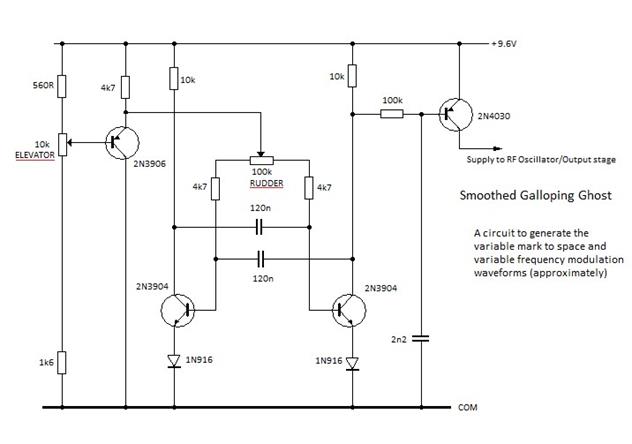
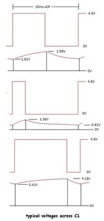
The circuit
above left is designed for pulsing the transmitter RF stage. The 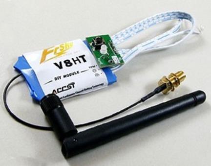 waveforms picture (right) refers to
the voltage ripple across C1 in Fig 7a. produced
by different Mark/Space ratios arriving at the receiver.
waveforms picture (right) refers to
the voltage ripple across C1 in Fig 7a. produced
by different Mark/Space ratios arriving at the receiver.
The picture left, shows the FrSky Do It Yourself 2.4 Gigahertz transmit module. This unit can be used to convert Vintage R/C transmitters or home assembled Model Radio Control equipment to a UK acceptable form for club and organized flying/boating events.
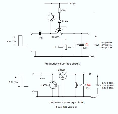
Regarding the 10K elevator pot in the pulse circuit above, it may be possible to use one of the two circuits (right) to convert the variable pulse rate into a varying voltage to drive a second Actuator (servo). This could be used for an elevator control.
HISTORY OF THE FIRST PROPORTIONAL FEEDBACK SERVOS. THEY WERE ANALOGUE ! !
(the following circuits relating to Analogue servos are for discussion only. They are not intended as construction projects)
Mark/Space pulsing at the transmitter began to get faster. This smoothed out the flapping effect of the actuators. It became apparent that the receiver output(s) were beginning to look like a simple moving voltage with some ripple on it. Move the joystick to the right and the Rx output would rise by more than a volt. Move the joystick to the left and the Rx output voltage would fall by more than a volt.
The first feedback servos were borne!
Surprisingly
the ‘servo mechanics’ were very similar to modern day ‘digital’ versions. A
small 20mm electric motor driving a set of gears to a rotary push rod output
arm. Gear ratio was around 270:1 which gave lots of push and quick transit time
over the 90 degrees of the output arm. The output arm shaft internally also had
a bronze wiper attached which was in contact with a 270 degree potentiometer.
Analogue servo 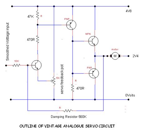 amplifiers
were very simple and often used only four transistors as in the possible
circuit to the left. The output voltage of the receiver, which moved up and
down with joystick movement was applied to the input of the servo amplifier.
The servo amp would drive the electric motor until the feedback voltage from
the pot was the same as the input voltage, resulting in motor drive switching
off. The servo output arm faithfully followed the joystick position.
amplifiers
were very simple and often used only four transistors as in the possible
circuit to the left. The output voltage of the receiver, which moved up and
down with joystick movement was applied to the input of the servo amplifier.
The servo amp would drive the electric motor until the feedback voltage from
the pot was the same as the input voltage, resulting in motor drive switching
off. The servo output arm faithfully followed the joystick position.
Analogue
Servos were a product
of the late 1950s. Transistors were predominately Germanium types. Perhaps
present day Silicon transistors would 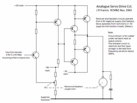 improve performance of this simple
amplifier. A pioneer of analogue servos was Doug Bolton. He designed and
used a servo with only three transistors ! These were
the days of simplicity !
improve performance of this simple
amplifier. A pioneer of analogue servos was Doug Bolton. He designed and
used a servo with only three transistors ! These were
the days of simplicity !
So What went wrong with analogue servos ?
The analogue servos themselves were simple and cost effective. The circuitry was well within the home build category at the time. The real problem was with the rest of the analogue R/C system. Generating up to four analogue servo channels at the transmitter with complete isolation from each other proved difficult. Invariably, one servo movement would ‘slightly’ effect one or more positions of the other servos. Producing any more than four servo channels would have been technically challenging. (I don’t recall an analogue R/C system with more than four servos).
In order to produce ‘smooth’ voltage outputs at the receiver, large value capacitors were used at the servo outputs in order to produce a level voltage. Unfortunately these smoothing capacitors also slowed down the inputs to the servos. This resulted in a fractional delay between moving the joystick at the transmitter and the servos moving.
Analogue Radio Control lived a short life (perhaps only two years) but this was an important life in the history of Radio Control Modelling.
The
following circuit (right) may
have helped to provide a more instantaneous servo response to  transmitter
joystick movement. The circuit would allow much lower values of smoothing
capacitor at the receiver to be
transmitter
joystick movement. The circuit would allow much lower values of smoothing
capacitor at the receiver to be 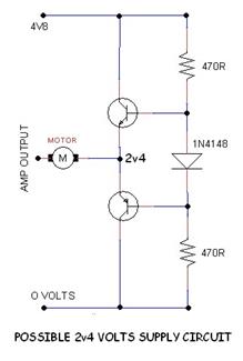 used. This would have minimised the
joystick to servo response. Voltage ‘ripple’ would be present at the receiver
outputs but lost before input to the servo amplifier via this in-line circuit.
used. This would have minimised the
joystick to servo response. Voltage ‘ripple’ would be present at the receiver
outputs but lost before input to the servo amplifier via this in-line circuit.
The circuit left may also have helped giving an electronic 2.4 volt supply for the servo motor. These early servo amps required four wires. (the extra wire was from the nicad battery centre tap.) It became very fashionable to have only three wire servos.
This circuit would have produced three wire Analogue Servos.
The short life of Analogue Radio Control Systems was abruptly brought to an end by the inventiveness of two NASA space engineers. Doug Spreng and Don Mathes. They invented and developed the Digital R/C system which is now 50 years old and to this day is still used by many professional R/C manufacturers.
The Digital R/C system solved all of the problems of analogue proportional Radio Control. Servo channels were transmitted and received sequentially which completely isolated each servo control input. Up to nine servos could be used with digital systems. There was no time delay between joystick movement and servo movement. All of the problems of the Analogue Radio Control Systems had been solved by this new technology and manufacturers dropped Analogue Radio Control Systems, like a ‘Hot Brick’ !
It is interesting that a small UK electronic kit supplier called Aercon Developments listed a servo kit suitable for Digital Radio Control systems in the early 1960s. It used SLM mechanical parts (UK) and after assembly, compared very well alongside commercial servos of the time. Visually there was no difference in the servo movement and operation except…… with the loss of transmitter signal… The servo self centred itself ! There was no schematic included with the kit instructions but looking at the PCB layout. It was quite definite that the amplifier was of the analogue type shown above.
AN AUTOMATIC CHARGER FOR 2 VOLT GLOW BATTERIES
This
simple circuit charges ‘part-charged’ two-volt glow batteries in an hour or
two, with auto slow-down to trickle charge. (The charge rate gradually reduces
toward the end of charge, to minimise battery ‘gassing’). The power input is
taken from the 12-volt field starter battery (or
car battery). Both input and output are polarity reverse 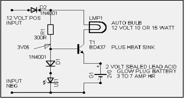 ‘safe’ and the green LED will only
illuminate with correct input and output connections. The Car Bulb LMP1
indicates charge, taking place and its illumination intensity shows the level
of charge. Bright is fast charge, Dull is slow charge and No illumination is
charge complete with ‘Trickle charge’. The glow battery can be left in the
trickle charge condition indefinitely (for a convenient time to unplug!) as the
trickle charge eventually drops to less than 25 milliamps. The LED US1 is used
as a voltage source for the base of T1, so care must be taken with substitutes.
The one used in the prototype was a ‘Kingbright’ superbright 5mm green! LED, which gives a foreword voltage
(Vf) of 2.3 volts (in this
circuit). D1 adds another 0.75 volts to the base of T1. The voltage across US1
can easily be measured after connecting the input leads of the circuit. (red LEDs give a lower Vf so don’t
use). All of the other components are non-critical. NOTE….if the glow battery
is severely discharged, (to be avoided for long battery life!) it may take a
minute or two for the green LED to illuminate. The ‘Hawker Cyclonâ’
glow-battery quotes 2000 charge cycles and 10 years life with sensible
charging!
‘safe’ and the green LED will only
illuminate with correct input and output connections. The Car Bulb LMP1
indicates charge, taking place and its illumination intensity shows the level
of charge. Bright is fast charge, Dull is slow charge and No illumination is
charge complete with ‘Trickle charge’. The glow battery can be left in the
trickle charge condition indefinitely (for a convenient time to unplug!) as the
trickle charge eventually drops to less than 25 milliamps. The LED US1 is used
as a voltage source for the base of T1, so care must be taken with substitutes.
The one used in the prototype was a ‘Kingbright’ superbright 5mm green! LED, which gives a foreword voltage
(Vf) of 2.3 volts (in this
circuit). D1 adds another 0.75 volts to the base of T1. The voltage across US1
can easily be measured after connecting the input leads of the circuit. (red LEDs give a lower Vf so don’t
use). All of the other components are non-critical. NOTE….if the glow battery
is severely discharged, (to be avoided for long battery life!) it may take a
minute or two for the green LED to illuminate. The ‘Hawker Cyclonâ’
glow-battery quotes 2000 charge cycles and 10 years life with sensible
charging!
CARAVAN SECURITY LIGHT?
 OK! Not directly associated with model electronics but as many
modellers have a caravan, then this little circuit could be of interest. The
prototype was assembled on Veroboard and inserted in
place of the bulb in the awning light. It gives a bright looking light that
can be left switched ON for up to six months! Using just the internal
caravan battery. It gives the impression that the caravan is occupied which
adds to security. The prototype used 5mm Ulta-bright
yellow LEDs from Rapid Electronics at 15p each. They drop 1.85 volts each at 15
milliamps. The resistor is a 0.25 Watt type. There are now Ulta-bright
white and blue LEDs which are being used for front lights of bicycles!
Providing the volt drop is similar then these could be used or a resistor value
change to compensate. Another idea was to place the device in a small plastic
box with wire connector, to plug into a 12 volt interior socket in the caravan.
The unit could then be placed near the front blinds or curtains to suggest
there was an interior light on. Wherever you park your caravan, this device
will help with unwanted callers! For Months!! Note that commercially
available LED lamps are now appearing on the market with similar spec.
OK! Not directly associated with model electronics but as many
modellers have a caravan, then this little circuit could be of interest. The
prototype was assembled on Veroboard and inserted in
place of the bulb in the awning light. It gives a bright looking light that
can be left switched ON for up to six months! Using just the internal
caravan battery. It gives the impression that the caravan is occupied which
adds to security. The prototype used 5mm Ulta-bright
yellow LEDs from Rapid Electronics at 15p each. They drop 1.85 volts each at 15
milliamps. The resistor is a 0.25 Watt type. There are now Ulta-bright
white and blue LEDs which are being used for front lights of bicycles!
Providing the volt drop is similar then these could be used or a resistor value
change to compensate. Another idea was to place the device in a small plastic
box with wire connector, to plug into a 12 volt interior socket in the caravan.
The unit could then be placed near the front blinds or curtains to suggest
there was an interior light on. Wherever you park your caravan, this device
will help with unwanted callers! For Months!! Note that commercially
available LED lamps are now appearing on the market with similar spec.
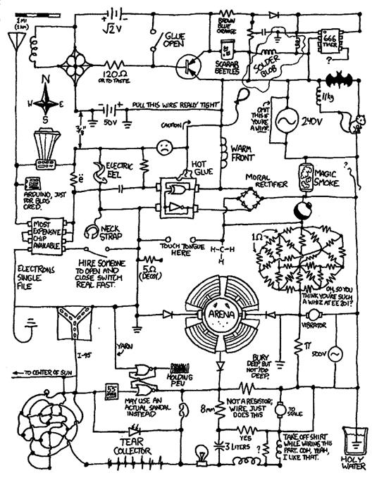
AN INTERESTING 2.4TRILLlANHz TRANSMITTER CIRCUIT BY RANDAL MUNROE.
Randal Munroe worked on robot technology at NASA’s Langley Research Labs. Randal has kindly let me display the circuit to the left.
Unfortunately, Randal went missing while working on the construction of his prototype. It is believed he was trying to connect the wiring at the bottom left of the circuit. It is thought that he ran out of wire.
Randal hopes that the publication of his circuit will inspire other electronic enthusiasts to help develop this new ground breaking technology.

Thanks for reading.